Engineers are available to assist.

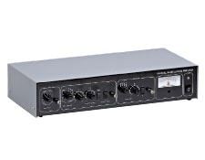
This analogue dual phase lock-in amplifier uses advanced technology to create a high performance instrument that is both versatile and easy to use. Lock-in amplifiers are used to measure the amplitude and phase of signals buried in noise by using the process of synchronous detection to recover the signals. The amplifier achieves this by acting as a narrow-bandpass filter that removes much of the unwanted noise while allowing through the signal that is to be measured. The frequency of the signal to be measured and thus the passband region of the filter is set by a reference signal, which has to be supplied to the lock-in amplifier along with the unknown signal. The reference signal must be at the same frequency as the modulation of the signal to be measured. The front panel has three adjustment sections: Input, Output, and Reference. Power: 115V AC, 230V AC; 50-60Hz; 10VA max. Operating Temperature Range: 0-50°C. Amplifier operation can be split into 4 stages: an input gain stage, the reference circuit, a demodulator and a low pass filter.
The Input Signal Channel amplifies the input signal to a level suitable for the demodulator. High performance, low-noise, broadband amplifiers are used throughout. The input circuit can accept a differential or single-ended input via the front panel signal input BNC. Jumper options within the unit allow the outer BNC contact or screen to act as a high impedance differential input, as a low impedance (100 ohms) differential input or allow it to be connected to ground for single-ended operation. Through the careful design of the lock-in, up to ±10V of DC offset is allowed before saturation for gain settings from 1V to 300μV, ±1V of DC offset for gain settings from 100μV to 10μV and ±300mV of DC offset for the gain setting of 3μV.
The output of the signal input stage is processed using two very high bandwidth demodulators each operating 90° apart from each other to produce the X and Y signals. The X and Y outputs from the demodulator are passed through two first order, low pass filters and then amplified. The X and Y signals are combined to produce R the modulus signal, where R=(x2+y2)^½, before output via a front panel BNC.
The Reference Channel input circuitry uses a phase locked loop to lock on to a range of signals, such as TTL pulses or sinusoidal waveforms. A phase shifting circuit allows the reference signal to be moved with relation to the signal input. Signals at both the reference frequency and twice the reference frequency can be monitored.
Note: This lock-in amplifier can be damaged if operated with the mains voltage selector incorrectly set. The voltage is set to 115V by default and must be changed if used in countries with 220V electrical mains. The voltage selection is marked on the back label of the unit and the selection switch is mounted inside. For more details on accessing and changing the voltage selection, please refer to the user manual included with the lock-in amplifier.


or view regional numbers
QUOTE TOOL
enter stock numbers to begin
Copyright 2023 | Edmund Optics, Ltd Unit 1, Opus Avenue, Nether Poppleton, York, YO26 6BL, UK
California Consumer Privacy Act (CCPA): Do Not Sell or Share My Personal Information
California Transparency in Supply Chains Act