


Distortion
Authors: Gregory Hollows, Nicholas James
This is Section 3.3 of the Imaging Resource Guide.
The term distortion is often applied interchangeably with reduced image quality. However, distortion is an individual aberration that does not reduce the information in the image; most aberrations mix information together to create image blur, distortion simply misplaces information geometrically. This means that known distortion can be mapped or calculated and removed from an image, whereas information from other aberrations is lost and cannot easily be recreated. More details on other aberrations can be found in Aberrations. Note that in high distortion environments, some information and detail can be lost due to the change in resolution associated with magnification or because too much information is crowded onto a single pixel.
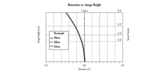
Distortion is a monochromatic optical aberration describing how the magnification in an image changes across the field of view (FOV) at a fixed working distance (WD); this is critically important in precision machine vision and gauging applications. Distortion is different from parallax, which is the change in magnification (FOV) with WD (more on parallax is provided in The Advantages of Telecentricity). Note that distortion varies with wavelength, as shown in Figure 1 and that when calibrating distortion out of a machine vision system, the wavelength of illumination must be known. Curves like the one in Figure 1 are helpful to calibrate out distortion.
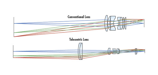
As with other aberrations, distortion is determined by the optical design of the lens. Lenses with larger FOVs will exhibit greater amounts of distortion because of the cubic field dependence. Distortion is a third-order aberration that, for simple lenses, increases with the third power of the field height; larger FOVs (a result of low magnification or short focal length) are more susceptible to distortion than smaller FOVs (high magnification or long focal length). The wide FOVs achieved by short focal length lenses must be weighed against the aberrations introduced to the system (such as distortion). In contrast, telecentric lenses typically have little distortion, which is a consequence of the way in which they function. It is important to note that when designing a lens to have minimal distortion, the maximum achievable resolution can decrease. To minimize distortion while maintaining high resolution, the complexity of the system must be increased by adding elements to the design or by utilizing more complex optical glasses.

Figure 1: A distortion plot showing the variance of distortion with respect to wavelength.
How is Distortion Specified?
Distortion is specified as a percentage of the field height. Typically, ±2 to 3% distortion is unnoticed in a vision system if measurement algorithms are not used. In simple lenses, there are two main types of distortion: negative, barrel distortion, where points in the FOV appear too close to the center; and positive, pincushion distortion, where points are too far away. Barrel and pincushion refer to the shape of the field when distorted, shown in Figure 2.

Figure 2: An illustration of positive and negative distortion.
Distortion is calculated simply by relating the Actual Distance (AD) to the Predicted Distance (PD) of the image using Equation 1. This is done by using a pattern such as dot target.
Note that while distortion runs negative or positive in a lens, it is not necessarily linear across the image. Additionally, distortion changes as wavelength changes. Finally, distortion can also change with changes in working distance. Ultimately, it is important to consider each lens used for an application to guarantee the highest level of accuracy when looking to remove distortion from a system.
Examples of Distorted Curves
Figure 3 shows negative, or barrel, distortion in a 35mm lens system. In this example, all the wavelengths analyzed have almost identical distortion, thus wavelength-related issues are not present.

Figure 3: Negative, or barrel, distortion in a lens.
In Figure 4, an interesting set of distortion characteristics is seen: there is separation in the amount of distortion for the different wavelengths, and both negative and positive distortion is present. Distortion of this nature is referred to as wave, or moustache, distortion. This is often seen in lenses designed for low levels of distortion, such as those designed for measurement and gauging applications. In this scenario, calibrating the system so that distortion is removed requires special consideration for applications where different wavelengths are used.

Figure 4: A wave, or mustache, distortion in a lens.
Geometric Distortion vs. TV Distortion: An Important Difference
In lens datasheets, distortion is usually specified in one of two ways: radial, geometric distortion or RIAA TV distortion. Geometric distortion is the distance between where points appear in the distorted image and where they would be in a perfect system. In practice, this can be measured using a distortion dot target. The difference between the distance from the center of the target to any dot in the FOV and the distance from the center of the image to the same, now misplaced dot (shown in Figure 5), provides the radial distortion percentage calculated with Equation 1.

Figure 5: Calibrated target (red circles) vs. imaged (black dots) dot distortion pattern.
The measurement of TV distortion is specified by an RIAA imaging standard and is determined by imaging a square target that only fills the vertical FOV. The difference in height between the corners and the center edge of the square is used to calculate the TV distortion with Equation 2; this is the apparent straightness of a line appearing at the edge of the image, which is the geometric distortion at a single field point.
By only specifying distortion at one point in the field, it is possible to misrepresent a non-zero distortion lens as having 0% distortion. In Figure 4, a 0% intercept can be found for any of the wavelengths shown. However, when the full image circle is considered, the lens has non-zero distortion. An example of how TV distortion can be found is shown in Figure 6.

Figure 6: TV distortion with both barrel and pincushion distortion.
Shown in Figure 4, manufactured, compound imaging lens assemblies have distortion that is not necessarily monotonic and can change signs across the FOV, which is why radial distortion plots are preferable to the single RIAA value. Because of how it is specified, TV distortion seems much lower than the maximum geometric distortion of the same lens, thus it is important to be aware of the type of distortion being specified when choosing the most appropriate lens for an application.
Keystone Distortion
In addition to the previous distortion types mentioned, which are inherent to the optical design of a lens, improper system alignment can result in keystone distortion, which is a manifestation of parallax (shown in Figure 7).


Figure 7: An example of keystone distortion in a lens layout (a) and as it manifests in the image plane (b).
When calibrating an imaging system against distortion, keystone distortion must be considered in addition to radial geometric distortion. Although distortion is often thought of as a cosmetic aberration that can be removed, it should be carefully considered against other system specifications when choosing the right lens. In addition to the potential for a loss in image information, algorithmic distortion correction takes additional processing time and power, which may not be acceptable in high speed or embedded applications.


or view regional numbers
QUOTE TOOL
enter stock numbers to begin
Copyright 2023 | Edmund Optics, Ltd Unit 1, Opus Avenue, Nether Poppleton, York, YO26 6BL, UK
California Consumer Privacy Acts (CCPA): Do Not Sell or Share My Personal Information
California Transparency in Supply Chains Act
This content may include material that has been generated or modified using artificial intelligence (AI).
The FUTURE Depends On Optics®