


Imaging Electronics 101: Camera Resolution for Improved Imaging System Performance
Camera resolution and contrast play an integral role in both the optics and electronics of an imaging system. Though camera resolution and contrast may seem like optical parameters, pixel count and size, TV lines, camera MTF, Nyquist limit, pixel depth/grayscale, dynamic range, and SNR contribute to the quality of what a user is trying to image. With tech tips for each important parameter, imaging users from novice to expert can learn about camera resolution as it pertains to the imaging electronics of a system.
Pixel Count and Pixel Size
To understand a camera’s pixel count and pixel size, consider the Allied Vision Stingray F-145 FireWire camera series. Each F-145 contains a Sony ICX285 sensor of 1392 x 1040 (horizontal x vertical) pixels on a 9.0mm x 6.7mm sensor. If one imagines the field of view as a rectangle divided into 1392 x 1040 squares (Figure 1), then the minimum resolvable detail is equal to two of these squares, or pixels (Figure 2). Tech Tip #1 is: The more pixels within a field of view (FOV), the better the resolution. However, a large number of pixels requires either a larger sensor or smaller-sized individual pixels. This leads to Tech Tip #2: Using a larger sensor to achieve more pixels means the imaging lens magnification and/or or field of view will change. Conversely, if smaller pixels are used, the imaging lens may not be able to hold the resolution of the system due to the finite spatial frequency response of optics, primarily caused by design issues or the diffraction limit of the aperture.
The number of pixels also affects the frame rate of the camera. For example, each pixel has 8-bits of information that must be transferred in the reconstruction of the image. Tech Tip #3: The more pixels on a sensor, the higher the camera resolution but lower the frame rate. If both high frame rates and high resolution (e.g. many pixels) are required, then the system price and set up complexity quickly increases, often at a rate not necessarily proportional to the number of pixels.
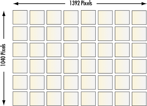
Figure 1: Illustration of Pixels on a Camera Sensor
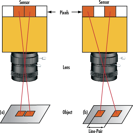
Figure 2: Pair of Pixels Unresolved (a) vs. Resolved (b)
TV Lines
In analog CCD cameras, the TV Line (TVL) specification is often used to evaluate resolution. The TVL specification is a unit of resolution based on a bar target with equally spaced lines. If the target is extended so that it covers the FOV, the TVL number is calculated by summing all of the resulting lines and spaces. Equations 1 and 2 provide simple calculations for determining horizontal (H) and vertical (V) TVL. Included in Equation 1 is a normalization factor necessary to account for a sensor's 4:3 aspect ratio. Figure 3 shows an IEEE approved testing target for measuring TVLs of a system.
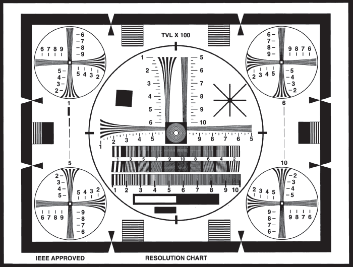
Figure 3: IEEE Approved Target for Measuring TV Lines (TVLs)
Modulation Transfer Function (MTF)
The most effective means of specifying the resolution of a camera is its modulation transfer function (MTF). The MTF is a way of incorporating contrast and resolution to determine the total performance of a sensor. A useful property of the MTF is the multiplicative property of transfer functions; the MTF of each component (imaging lens, camera sensor, display, etc.) can be multiplied to get the overall system response (Figure 4).
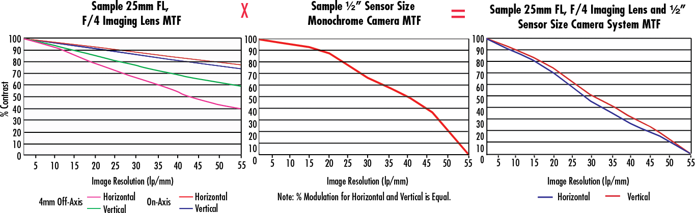
Figure 4: System MTF is the Product of the MTF of Each Individual Component
The MTF takes into account not only the spatial resolution of the number of pixels/mm, but also the roll off that occurs at high spatial frequencies due to pixel cross talk and finite fill factors. Tech Tip #4: It is not the case that a sensor will offer 100% contrast at a spatial frequency equal to the inverse of its pixel size. For a complete discussion of MTF and its importance, view Modulation Transfer Function.
Nyquist Limit
The absolute limiting resolution of a sensor is determined by its Nyquist limit. This is defined as being one half of the sampling frequency, a.k.a the number of pixels/mm (Equation 3). For example, the Sony ICX285 is a monochrome CCD sensor with a horizontal active area of 9mm containing 1392 horizontal pixels each 6.45μm in size. This represents a horizontal sampling frequency of 155 pixels/mm (1392 pixels / 9mm = 1mm / 0.00645 mm/pixel = 155). The Nyquist limit of this calculates to 77.5 lp/mm. Keep in mind that image processing methods exist, such as sub-pixel sampling, which enable a user to statistically extrapolate higher resolution than the Nyquist limit in the special case of edges and other geometrically simple figures. At the Nyquist limit, contrast is phase dependent for a constant incident square wave (imagine one pixel on, one pixel off, or each pixel with half a cycle). It is, therefore, common to include the Kell factor (∼0.7), which reflects the deviation of the actual frequency response from the Nyquist frequency. Most importantly, the Kell factor compensates for the space between pixels. Tech Tip #5: Sampling at spatial frequencies above the system’s Nyquist limit can create spurious signals and aliasing effects that are undesirable and unavoidable.
Pixel Depth/Grayscale
Often referred to as grayscale or, (less precisely) the dynamic range of a CCD camera, pixel depth represents the number of steps of gray in the image. Pixel depth is closely related to the minimum amount of contrast detectable by a sensor. In analog cameras, the signal is a time varying voltage proportional to the intensity of the light incident on the sensor, specified below the saturation point. After digitizing, this continuous voltage is effectively divided into discrete levels, each of which corresponds to a numerical value. At unity gain, light that has 100% saturation of the pixel will be given a value of 2N-1, where N is the number of bits, and the absence of light is given a value of 0. Tech Tip #6: The more bits in a camera, the smoother the digitization process. Also, more bits means higher accuracy and more information. With enough bits, the human eye can no longer determine the difference between a continuous grayscale and its digital representation. The number of bits used in digitization is called the bit depth or pixel depth.
For an example of pixel depth, consider the Sony XC Series, which offers 256 shades of gray, and the Edmund Optics USB 2.0 CMOS series, which are available in 8-bit (256 grayscale) and 10-bit (1024 grayscales) models. Generally, 12-bit and 14-bit cameras have the option of running in a lower pixel depth mode. Although pixel depths above 8-bits are useful for signal processing, computer displays only offer 8-bit resolution. Thus, if the images from the camera will be viewed only on a monitor, the additional data does nothing but reduce frame rate. Figure 5 illustrates different pixel depths. Notice the smooth progression from gray to white as bit depth increases.

Figure 5: Illustration of 2-Bit (Top), 4-Bit (Middle), and 8-Bit (Bottom) Grayscales
Dynamic Range
Dynamic range is the difference between the lowest detectable light level and the highest detectable light level. Physically, this is determined by the saturation capacity of each pixel, the dark current or dark noise, the ADC circuits, and gain settings. Tech Tip #7: For high dynamic ranges, more bits are required to describe the grayscale in a meaningful fashion. However, it is important to note that, with consideration of the signal-to-noise-ratio, using 14 bits to describe a 50dB dynamic range gives redundant bits and no additional information.
Signal-to-Noise Ratio (SNR)
The signal-to-noise ratio (SNR) is closely linked to the dynamic range of a camera. Tech Tip #8: A higher SNR yields a higher possible number of steps in the grayscale (higher contrast) produced by a camera. The SNR is expressed in terms of decibels (dB) in analog systems and bits in digital systems. In general, 6dB of analog SNR converts to 1-bit when digitized. For digital or analog cameras, X bits (or the equivalent in analog systems) correspond to 2X grayscales (i.e. 8-bit cameras have 28 or 256 gray levels).
There are two primary sources for the noise in camera sensors. The first is imperfections in the chip, which result in non-uniform dark current and crosstalk. The second is thermal noise and other electronic variations. Chip imperfections and electronic variations reduce camera resolution and should be monitored to determine how to best compensate for them within the imaging system.
The basics of camera resolution can be divided into parameters of pixel count and size, TV lines, camera MTF, Nyquist limit, pixel depth/grayscale, dynamic range, and SNR. Understanding these basic terms allows a user to move from being a novice to an imaging expert. To learn more about imaging electronics, view our additional imaging electronics 101 series pertaining to camera sensors, camera types, and camera settings.


or view regional numbers
QUOTE TOOL
enter stock numbers to begin
Copyright 2023 | Edmund Optics, Ltd Unit 1, Opus Avenue, Nether Poppleton, York, YO26 6BL, UK
California Consumer Privacy Acts (CCPA): Do Not Sell or Share My Personal Information
California Transparency in Supply Chains Act
This content may include material that has been generated or modified using artificial intelligence (AI).
The FUTURE Depends On Optics®