


Resolution and MTF Testing
This is Section 12.1 of the Imaging Resource Guide.
Six-hundred and forty (640) pixels were the standard for camera sensors only a few decades ago. It is common to see more than six million pixels on sensors today. When sensors only offered several hundred pixels, it was customary for the imaging lens to outperform the sensor. Today however, pixels on sensors are getting smaller and more numerous. To keep up with sensors, lens manufacturers have increased their lens selections, while pushing the boundaries of lens design technology and manufacturing. To take advantage of pixels decreasing in size and increasing in number, lens performance must increase. Selecting the right lens requires understanding and proper characterization of a lens’s performance.
To measure how well a lens perform requires the use of correct metrology. To characterize lens performance, a set of objectives based on lens specifications must be designated before selecting test methods. It is important to remember that no one test method can fully characterize every lens specification. Moreover, many tests useful for characterizing performance exclude real-world and often application specific, external effects. Therefore, a test plan that uses multiple methods may be necessary.
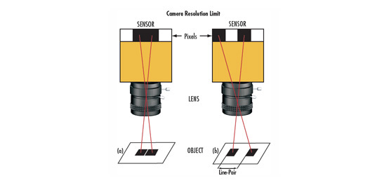
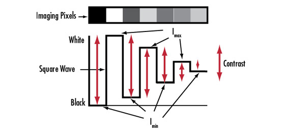
Resolution is often the most important specification for an imaging lens; it is a continuous function that tells the user how small a detail can be before it’s indistinguishable from its surroundings at a specific contrast level. The performance of a lens can vary across different points within the image and can also vary with working distance (WD), f/#, and other parameters. When measuring resolution and contrast it is important to manage expectations and set reasonable system boundaries. Some resolution test methods can also reveal additional information about other parameters such as distortion and relative illumination. Common tests for lens resolution include reverse projection testing, modulation transfer function (MTF) testing, slanted edge MTF testing, and camera testing. Each of these methods provides a unique set of benefits and drawbacks.
Reverse Projection Testing
In reverse projection testing, a lens test projector is used. The pattern from a high accuracy test target is placed at the image plane and is projected through an imaging lens to a specific WD (essentially, imaging in reverse) and observed in a dark room. Because the modulation of light through a lens is a reversible process, this method is a simple and effective test of resolution. This method is additionally useful because resolution specifications are already given as image space values. A common test target used in reverse projection is the USAF 1951 target, which consists of a several orthogonally oriented bars of increasing frequency that spiral into the center. The bars are dispersed across the entire field allowing operators to focus the lens to optimize resolution at specific field regions. As such, this method can be used to test multiple field points at once.
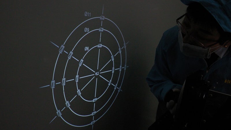
Figure 1: An operator performing a reverse projection test. The circles labeled 11, 9, and 6 correspond to image circles of 2/3”, 1/1.8”, and 1/3” sensors, respectively.
Reverse projection is low-cost and a fast method to test lens resolution and astigmatism. Operator training is relatively easy, and equipment cost is inexpensive compared to other methods. One important drawback of this test is the inability to measure contrast levels since this test method depends on operator eyesight. Human eyes can typically detect the lowest resolvable contrast, which is approximately 20%, but not specific contrast values.
Modulation Transfer Function (MTF) Testing
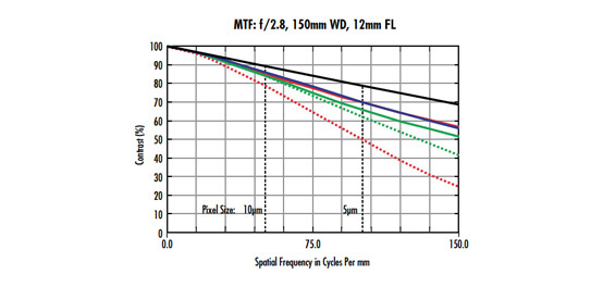
The most comprehensive representation of the resolution performance of an imaging lens is a MTF curve. MTF curves are used to directly compare the resolution of one lens to another. Commercial test benches are available that allow for the characterization of lenses within a three-dimensional coordinate system (Figure 2).
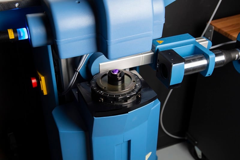
Figure 2: A slanted-edge MTF measurement. Multiple measurement areas can be concurrently tested.
An operator conducts an MTF test by passing an impulse signal through a lens, typically in the form of light from a point source against a dark background. Careful attention is paid to the position of the source and the location of the image. The impulse response is then used to determine a response at any spatial frequency up to the Nyquist (the highest, resolvable, sampled frequency). Because the testing environment is so tightly controlled, the measurements obtained are purely descriptive of the performance of the lens.
External phenomena, such as stray light and falloff , are not factored into system-level performance specifications and the actual achievable resolution may be less than what the MTF curve suggests. Calculations from an MTF test bench are, by definition, contrast as a function of spatial frequency within a one, two, or three-dimensional coordinate system.
Slanted-Edge MTF Testing
Slanted-edge MTF testing obtains the same system level information as MTF testing but more quickly, with more adaptability, and on less expensive equipment. Where regular MTF testing uses the Airy disk of a point source, magnified by an objective to fit the full sensor to remove any external MTF contributions, slanted-edge MTF testing uses a high contrast edge target positioned at an angle of several degrees. If only the MTF contribution of the lens is required, then all contributions from other components must be removed from the system level MTF by dividing them out (because contributions are multiplicative). The first step in obtaining the slanted-edge MTF is to measure the sigmoidal-shaped edge-spread function and its derivative to determine the line-spread function, which is then filtered, and Fourier transformed into the MTF curve.
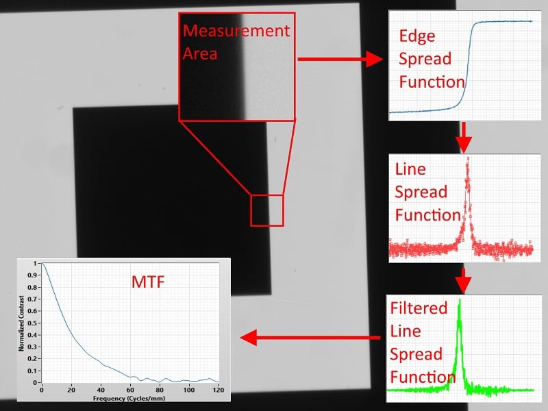
Figure 3: A slanted-edge MTF test generates MTF information from the line spread function of a slanted edge.
This process only works if the contrast transition of the edge target occurs of a scale four times smaller than the Nyquist limit. If an edge target has a transition of 100μm and the resolution goal is 100lp/mm, (5μm Nyquist sample size), then the edge target would be enough, if the magnification (m) is less than 0.0125X (see calculation).
\begin{align} \text{Transition Width}_{\small{\text{Image Space}}} \left[ \unicode[arial]{x03BC} \text{m} \right] < & \, \, \text{Nyquist Width} \left[ \unicode[arial]{x03BC} \text{m} \right] \div 4 \\\text{Transition Width}_{\small{\text{Object Space}}} \left[ \unicode[arial]{x03BC} \text{m} \right] \times m < & \, \, \text{Nyquist Width} \left[ \unicode[arial]{x03BC} \text{m} \right] \div 4 \\100 \unicode[arial]{x03BC} \text{m} \times m < & \, \, 5\unicode[arial]{x03BC} \text{m} \div 4 \\m < & \, \, \frac{5 \unicode[arial]{x03BC} \text{m}}{100 \unicode[arial]{x03BC} \text{m}} \div 4 \\m < & \, \, 0.0125 \end{align}
Camera Tests
"Camera test" is an umbrella term for all tests that use a camera. The slanted-edge MTF test is one specific camera test but it is not the only common camera test for resolution. Camera test methods can be adapted, using different techniques or equipment, to any real-word application to obtain system-level, environmentally relevant resolution information. These tests often use test targets that allow for a specific set of performance metrics to be tested at the correct image field positions and in the test environment. As sensors continue to have a greater number of smaller sized pixels, the optical and mechanical requirements of lenses made to interface with them must also improve. System and machine vision end users often misunderstand the effects that govern vision system performance. Understanding what information each test method provides, as well as the pros and cons for each, will ensure success.
| Method | Pros | Cons |
| Rear Projection |
Fast | Qualitative |
| Inexpensive | Poor diagnostic capabilities | |
| Operator friendly | Poor ability to control spectral content (response is photopic) | |
| Tests multiple field points concurrently | Hard to maintain accurate coordinate systems | |
| Quickly establish limiting resolution | Difficult to use for higher magnifications | |
| MTF | Off the shelt measurement instruments available | Calculated at one image point at a time |
| Higher-order aberrational content can be diagnosed | Insensitive to stray light and other environmental contrast degrading phenomena | |
| High accuracy and precision | Poor reproduction of most real-world illumination environments | |
| Most broadly-applicable "general use" test method | Expensive, easily misused equipment | |
| Slanted Edge MTF | Tests multiple field points concurrently | Target selection can be difficult for common magnification range (~0.05 - 0.01X) |
| Free and commercial software readily available | Sensitive to illumination uniformity | |
| Can use a standard (ISO 12233) or tweak to suit specific needs | System-level contribution from non-lens components can lead to large error bars (especially at high frequencies) | |
| Can be used to measure system level MTF including lens, camera, illumination, and any image processing algorithms | Easily misused | |
| Coordinate system of cameras shifts from tangenital and sagittal performance to horizontal and vertical | ||
| Camera Tests | Tests multiple field points concurrently | |
| The most application-specific approach | Little to no outside support | |
| Endlessly adaptable | Difficult to correlate | |
| Can be used to measure system-level performance including lens, camera, illumination, and any image processing algorithms |


or view regional numbers
QUOTE TOOL
enter stock numbers to begin
Copyright 2023 | Edmund Optics, Ltd Unit 1, Opus Avenue, Nether Poppleton, York, YO26 6BL, UK
California Consumer Privacy Acts (CCPA): Do Not Sell or Share My Personal Information
California Transparency in Supply Chains Act
This content may include material that has been generated or modified using artificial intelligence (AI).
The FUTURE Depends On Optics®