


ISO Drawings for Aspheric Lenses
Lens drawings are the primary tool for communicating manufacturing and testing requirements. They are used at all stages of the process of creating optics by designers, sales people, manufacturing engineers and technicians, metrologists, and quality assurance. It is critical that the drawing is interpreted identically by all who use the document, or the final product may not meet the intended specifications.
Fortunately, the International Organization for Standardization (ISO) has produced extensive documentation that clarifies the minutia of optical drawings. ISO 10110 contains content which details drawing preparation with sections covering subjects such as Surface Form Tolerances (ISO 10110-5), Centering Tolerances (ISO 10110-6) and Laser-Induced Damage (ISO 10110-17).
ISO 10110 outlines the format of lens drawings with standard locations for commonly used lens specifications, which makes it easy to find values once the layout becomes familiar.
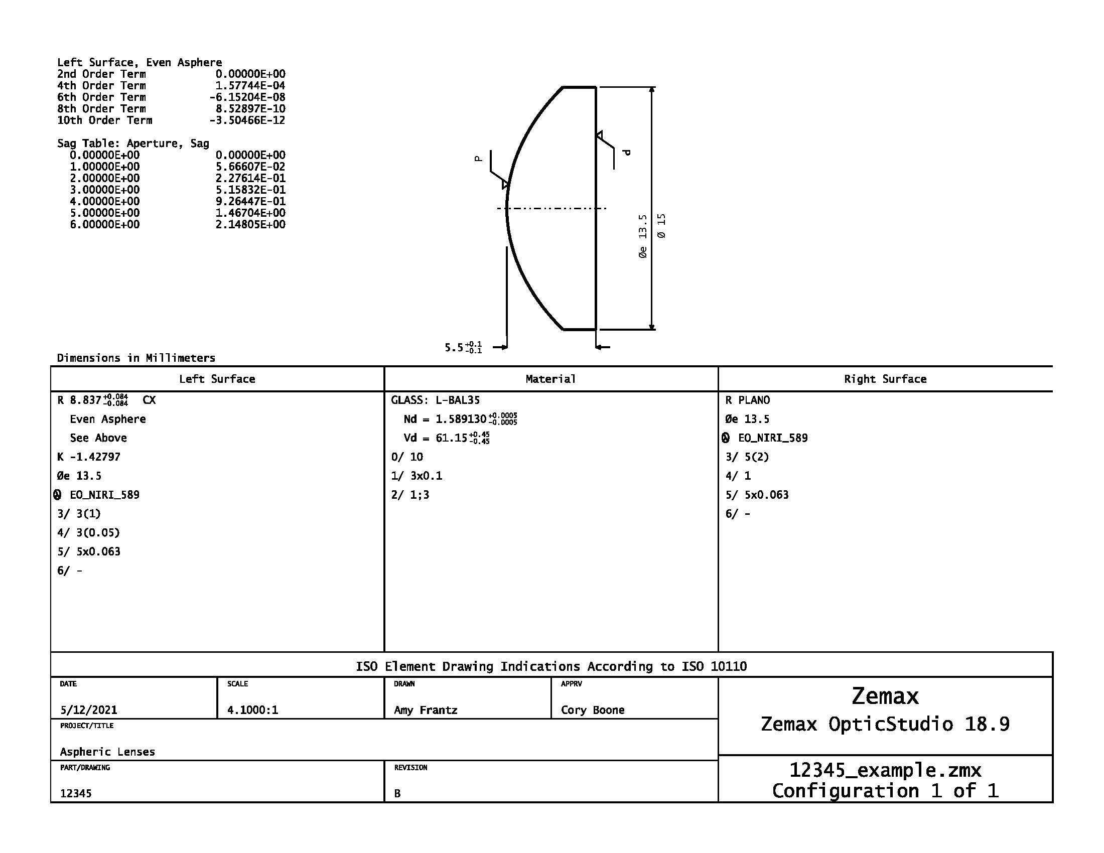
Figure 1: This typical ISO drawing of an aspheric lens follows the conventions defined in ISO 10110. Click here to download a PDF of this drawing for a closer look.
Figure 1 shows a typical asphere drawing according to ISO-10110, with a depiction of the lens in the top center section that may include basic parameters such as diameter and center thickness. The material information is contained in the central region, and the left and right lens surface parameters are contained in the central left and right boxes, respectively. The bottom section is left for details such as title, date, and revision iteration.
This drawing standard is valuable for standardizing spherical lens drawings, but it also ideal for communicating some parameters that are key to aspheric lens performance. ISO 10110-12 specifies how to describe aspheric surfaces on prints, while other sections clarify how to define critical parameters such as surface roughness, centration, slope error, and surface quality. The advantage of ISO is that all these values are clearly defined in the documentation, so there can be consensus between the customer and manufacturing without the need for a lengthy back and forth discussion.
Surface Roughness
Surface roughness can affect light scatter and laser damage threshold and is particularly important for aspheres that are being used to focus or collimate high powered lasers. Often, prints will attempt to specify this with an indication such as “surface roughness: 10Å.” This, however, is an incomplete specification and may lead to disagreements between manufacturers and customers. It is critical that the calculation of surface roughness is defined. A common way to define how roughness is calculated is to take the root mean square (RMS) of all data. Another way to define roughness uses the average value of all the available data. RMS surface roughness will be higher than the average surface roughness for the exact same set of data because it involves squaring of each data point and more heavily weights high values. ISO 10110-8 uses Ra to designate average roughness, Rq for RMS roughness for a sample length, and Sa and Sq for the average and RMS roughness for a sample area, respectively. Another concern is the spatial frequency band of errors that is being considered. Large form errors are not relevant to the parameter of surface roughness, so a minimum cutoff frequency must be defined to exclude irrelevant form errors. At very high frequencies, the data will approach the noise floor of the metrology, so a high frequency cutoff value should also be defined. ISO drawings use a checkmark symbol to designate the surface finish with either a "G" for a ground surface or a "P" for a polished surface. The surface finish for a simple polishing specification can be indicated with a "P1", "P2", "P3", or "P4", with P4 indicating the smoothest surface as outlined in ISO 10110-8. If a more specific tolerance is needed, the particular method of calculating surface roughness will be indicated to the right of the checkmark symbol. Between the calculation method and the checkmark, the maximum roughness for a polished surface is stated in units of microns, and underneath the checkmark, the frequency band is indicated (Figure 2). If no frequency band is specified for roughness, a range of 0.0025mm – 0.08mm is typically assumed.

Figure 2: This ISO surface roughness callout indicates a surface with < 16 microdefects per 10mm scan (as indicated by “P3”) and an RMS surface roughness (Rq) < 4μm over a spatial bandwidth of 1 - 0.003 mm.
Centration
The centering tolerance is described in ISO 10110-6. For a spherical lens, the tolerance on an individual surface is specified by a maximum tilt angle (σ) relative to a datum axis, which typically references the outer mechanical diameter of the lens. Aspheres that have a small amount of aspheric departures can also be specified this way. However, an asphere has an axis of symmetry rather than a spherical surface’s point of symmetry, so it is incomplete to only specify a tilt. ISO also includes the lateral displacement L to fully characterize an aspheric surface’s centration. The lateral displacement of the asphere is the distance from the point of rotational symmetry of the aspheric surface to the datum axis, which, as noted above, is typically defined by the outer mechanical diameter. The centering specification is written as "4/σ(L)". Fully characterizing an asphere’s centration allows the designer to more accurately predict the as-built performance of the lens as opposed to using the single value of a beam deviation or surface runout.
Surface Form
Surface form tolerances can generally be expressed the same for spherical and aspheric surfaces. The general form of the specification in ISO is "A(B/C) RMSx < D; λ = E". "A" represents the maximum power, or sagitta deviation, in terms of fringes. This can be omitted with a dash if a radius tolerance is used elsewhere on the drawing in place of a power tolerance or set equal to 0 if no power deviation is allowed. "B" is the maximum irregularity in fringes, which can again be omitted with a dash, and "C" is the rotationally-invariant irregularity, which is most commonly left out completely by simply not including the "/C" portion of the specification. It is also permissible to leave out "A(B/C)" entirely. If a tolerance on the RMS surface deviation is desired, "RMSx < D" may be included in the specification, with the "x" indicating the type of RMS calculation used, where "x" is either "t" for total RMS of the surface’s deviation from the nominal form, "I" for the RMS of the irregularity of the surface, or "a" for the RMS of the asymmetric irregularity. "D" is the limiting value for the RMS. If a fringe based on a wavelength of any value other than 546.07nm is desired, "λ = E" must be included where "E" is the wavelength. More detailed definitions of all these parameters are found in ISO 10110-5 and ISO 14999-4. If a different type of surface form tolerance is desired, such as a total peak to valley error, this can be included as a note on the drawing.
Slope Error
Polished aspheres are subject to sub-aperture manufacturing processes which can impart surface figure errors that are of a higher frequency than the errors typically found on conventionally manufactured spherical lenses. These mid-spatial errors, as they are often referred to, can have significant detrimental effects on an optical system and may need to be controlled with a slope error tolerance. Slope error is a measure of the difference in slope between a desired surface and the actual surface over a specified length or area. There are many important clarifications that need to be made when specifying this parameter to ensure the correct interpretation. These clarifications include the method of detrending the raw measurement data, the dimension of the tolerance (length or area), the spatial sampling interval, the sample length over which the slope is evaluated (this determines the frequency of interest), and whether the tolerance is a peak-to-valley or RMS. All of these are clearly defined in the ISO documentation, and can be called out directly beneath the surface form tolerances on the drawing.
Surface Quality
For those who are accustomed to specifying surface quality using the US Military Standard MIL-PRF-13830B, switching to ISO specifications can be a dramatic change. MIL-PRF uses two numbers in a Scratch-Dig system, where a number such as “60-40” is called out with 60 representing the scratch specification and 40 representing the dig specification. In this case, the 40 corresponds to a maximum physical diameter of 400µm in the size of a dig, but the 60 must be compared to a reference standard scratch. An optic must be inspected using specific lighting and viewing configurations, and it is the “apparent brightness” of the scratch on the optic that is compared to a standard. This test is subjective, and the physical size of the scratch is not controlled. In contrast to MIL-PRF-13830B, ISO 10110-7 calls out the maximum area of defects without distinguishing between scratches and digs, and is therefore often considered more objective and repeatable, but also more difficult and time-consuming to inspect and calculate. An ISO drawing typically has surface quality specified as 5/N x A, where "N" is the number of allowed imperfections and "A" is the square root of the maximum size of the area of imperfection in units of millimeters. ISO does allow for separating out long scratches and coating imperfections, but it is not required. ISO has the advantage of being more objective, but MIL-PRF has a cost advantage by allowing for more streamlined inspection. Fortunately, ISO drawings now allow for specifying surface quality using scratch-dig, so the designer is free to choose whichever method makes the most sense for the given application!
Conclusion
With multiple standards to choose from, it can be difficult to select a drawing standard, if any, to use. Aspheres in particular have many parameters that are important to the function of the lenses yet are open to interpretation depending on how they are specified. ISO provides a standard for asphere drawings that clearly defines important aspects of a lens such as roughness, centering, and slope error, and allows flexibility in other parameters such as surface quality.
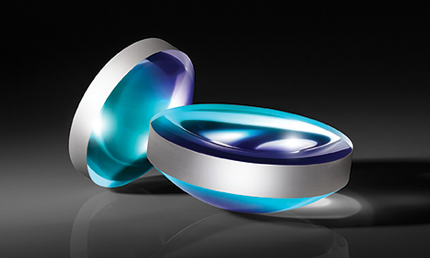
Aspheres from Edmund Optics®
Looking for aspheric lenses for your application? Edmund Optics® offers over 700 standard asphere designs available for immediate shipping, and custom aspheres can be manufactured for your specific needs. Whether you need prototypes or high volumes, Edmund Optics® engineers can create a solution for you.
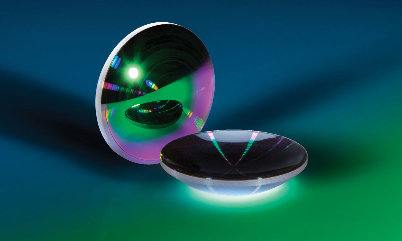
Precision Glass Molded Aspheric Lenses
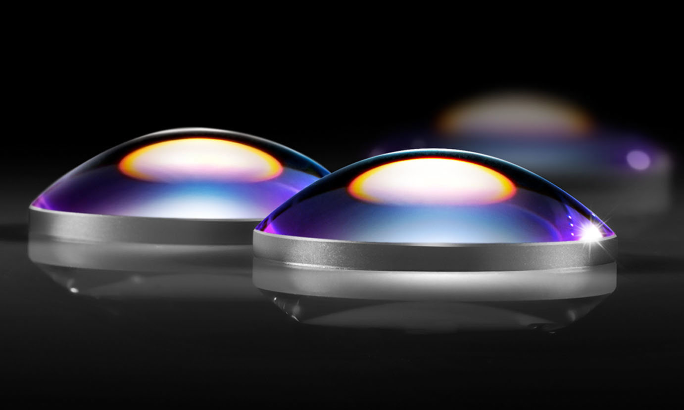
Small Diameter Lenses for Laser Collimation and Focusing
BUY NOW

More Resources
- How an Aspheric Lens is Made Video
- All About Aspheric Lenses
- High-End Asphere Design for Manufacturability Webinar Recording
- Aspheric Lens Irregularity and Strehl Ratio
- Aspherized Achromatic Lenses
- Edmund Optics Global Manufacturing Facilities Video
- Metrology at Edmund Optics: Measuring as a Key Component of Manufacturing Video


or view regional numbers
QUOTE TOOL
enter stock numbers to begin
Copyright 2023 | Edmund Optics, Ltd Unit 1, Opus Avenue, Nether Poppleton, York, YO26 6BL, UK
California Consumer Privacy Acts (CCPA): Do Not Sell or Share My Personal Information
California Transparency in Supply Chains Act
This content may include material that has been generated or modified using artificial intelligence (AI).
The FUTURE Depends On Optics®