


Machine Vision Filter Technology
Authors: Gregory Hollows, Nicholas James
Types of Filter Technology
This is Section 8.1 of the Imaging Resource Guide.
There are many different types of filters in machine vision that can be used to improve or change the image of the object under inspection. It is important to understand the different technologies behind the various types of filters to understand their advantages and limitations. Although there is a wide variety of filters, almost all can be divided into two primary categories: colored glass filters and coated interference filters.
Colored Glass Filters
Colored glass filters are incredibly common in machine vision, and are created by doping glass materials with elements that selectively change their absorption and transmission spectra. The dopants vary based on which wavelengths are considered for transmission, and the manufacturing process is nearly identical to standard optical glass manufacturing. Colored glass filters are advantageous for a several reasons: they are of relatively low cost when compared to interference filters and, more importantly, do not demonstrate any shift in wavelength transmission when used with wide angle lenses or at an angle. However, colored glass filters also typically feature wide cut-on wavebands, do not have curves that are as sharp or accurate as coated interference filters, and do not have transmission amounts as high as interference filters. Figure 1 shows the transmission curves for several common colored glass filters. Note that the filters feature wide cut-on wavebands and have relatively shallow slopes describing their transmission functions.

Figure 1: Transmission curves for several different colored glass filters.
Infrared (IR) cut-off filters can be either colored glass filters or a type of coated filter that is useful for both monochrome and color cameras. Since the silicon sensors in most machine vision cameras are responsive to wavelengths up to approximately 1µm, any IR light incident on the sensor from overhead fluorescent lights or other unwanted sources can create sensor inaccuracies. On a color camera, IR light will create a false color on the sensor that can degrade overall color reproduction. For this reason, many color imaging cameras come standard with IR-cut filters. With monochrome cameras, the presence of IR light will lower the contrast of the overall image but IR-cut filters are generally not built-in, unlike with color cameras. There are a multitude of other types of colored glass filters. For instance, daylight blue filters can be used for color balancing when polychromatic light sources and color sensors are used.
Coated Interference Filters
Coated filters typically offer sharper cut-on and cut-off transitions, higher transmissions, and better blocking than colored glass filters. In addition to colored glass filters, there are a range of coated filters, that include hard coated fluorescent filters, dichroic filters, and polarizing filters. Each coated filter undergoes a unique manufacturing process to ensure proper performance. Wavelength-selective optical filters are manufactured by depositing dielectric layers on a specific substrate of alternating high and low refractive indices. The surface quality and uniformity of the substrate establishes the baseline optical quality of the filter, along with setting wavelength limits where the transmission of the substrate material falls off. The dielectric layers produce the detailed spectral structure of a filter by creating constructive and destructive interference across a range of wavelengths, and by providing much sharper cut-off and cut-on bands compared to colored glass filters. Many types of hard coated filters exist, such as bandpass, longpass, shortpass, and notch filters, each with a specified blocking range and transmission range. Longpass filters are designed to block short wavelengths and pass long wavelengths.
Shortpass filters are the opposite, passing shorter wavelengths and blocking long. Bandpass filters pass a band of wavelengths, while blocking longer and shorter wavelengths that lie outside the passband. The inverse of a bandpass filter is a notch filter, which blocks a band of wavelengths and passes the longer and shorter. Transmission curve shapes for these filter types are shown in Figure 2.

Figure 2: Transmission curve examples of longpass and shortpass (a) and bandpass and notch filters (b)..
Filters designed for deep blocking (high Optical Density) and steep slopes (sharp transition from blocking to transmission) re used in applications where precise light control is critical. Most machine vision applications do not require this level of precision; typically, any filter with an Optical Density (OD) of 4 or greater is more precise than required and adds unnecessary cost. Because hard coated filters utilize optical interference to achieve such precise transmission and rejection bands, they introduce difficulties when used in machine vision applications. All interference filters are designed for a specific Angle of Incidence (AOI), generally 0° unless specifically designated otherwise. When used in machine vision, these filters are generally placed in front of the lens; doing such causes the filter to accept light coming from angles dictated by the angular field of view (AFOV) of the lens. Especially in the case of short focal length (large AFOV) lenses, the light that is transmitted through the filter will often display an unwanted effect known as blue shift. For example, a wide angle 4.5mm focal length lens will have a much larger blue shift than a narrow angle 50mm focal length lens. As the AOI on an interference filter increases, the optical path length through the filter layers increases, which causes the cut-on and cut-off wavelengths to decrease (Figure 3).

Figure 3a: Interference filters function based on the distance that light incident upon the filter travels. At the correct angle of incidence, the light waves incident on the filter destructively interfere, stopping them from passing through the filter. At a different angle, the destructive interference is not as effective.

Figure 3b: An example of blue shift, shown with a bandpass filter used at a 15˚ angle of incidence. Note not only the shift towards a lower center wavelength, but the shallowing of the slope as well. The dashed curve is ideal, when the filter is used at a 0˚ angle of incidence.
Therefore, at different field points in the image, the filter will behave differently by transmitting different wavelength ranges: the farther out in the field, the more pronounced the blue shift. In most cases, interference filters can still provide better filtering control over a colored glass filter, but be aware of the potential pitfalls when using an interference filter with a wide-angle lens.
Applications with Machine Vision Filtering
This is Section 8.2 of the Imaging Resource Guide.
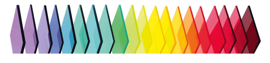
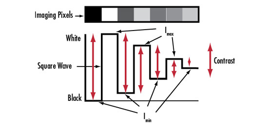
When designing a machine vision system, it is important to enhance the contrast of the inspected object’s features of interest. For an introduction to contrast, see the app note Contrast. Filtering provides a simple way to enhance the contrast of the image while blocking out unwanted illumination. There are many different ways filters can enhance contrast, and the filter type is dependent on the application. Some common filters used in machine vision are colored glass, interference, Neutral Density (ND), and polarization. Colored glass bandpass filters are some of the simplest filters available for drastically improving image quality. These filters work incredibly well at narrowing the waveband that is visible by the vision system, and are often less expensive than comparable interference filters. Colored glass filters work best when used to block out colors on the opposite side of the color wheel (Figure 4).

Figure 4: Color wheel demonstrating that warm colors should be used to filter out cool colors on the opposite side of the wheel.
Color Filters
Consider the example shown in Figure 5, where gel capsules are being inspected. As shown, two red capsules are on the outer sides of a pair of green capsules and under a white light backlight.
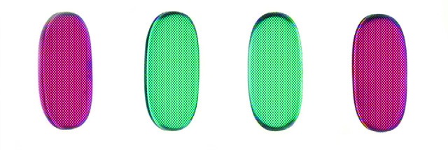
Figure 5: Four liquid capsules under inspection with the same vision system, shown here in color.
This is a sorting application where the pills need to be separated by color to reach their respective locations. Imaging the capsules with a monochrome camera (Figure 6) provides a contrast between the green and red capsules of only 8.7%, which is below the minimum advisable contrast of 20%. In this particular example, minor fluctuations in ambient light, such as individuals walking past the system, can decrease the already low contrast value of 8.7% enough so that the system is no longer capable of operating properly. Several solutions to this problem exist: a bulky and costly light baffling system can be built to completely enclose the inspection system, the entire lighting scheme of the system can be reworked, or a filter can be added to enhance the contrast between the green and red pills. In this instance, the simplest and most cost effective solution is to utilize a green colored glass filter in order to improve the contrast between the two different colored capsules. As shown in Figure 6, the contrast improves from 8.7% to 86.5%: an increase of nearly a factor of 10.
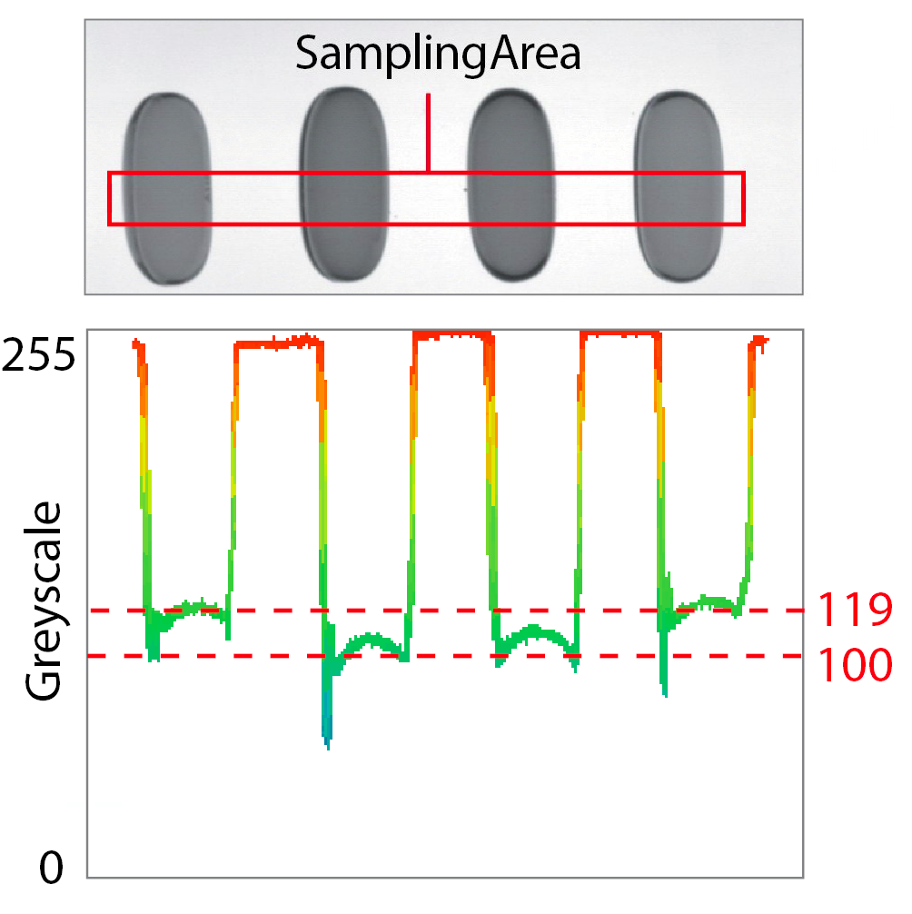
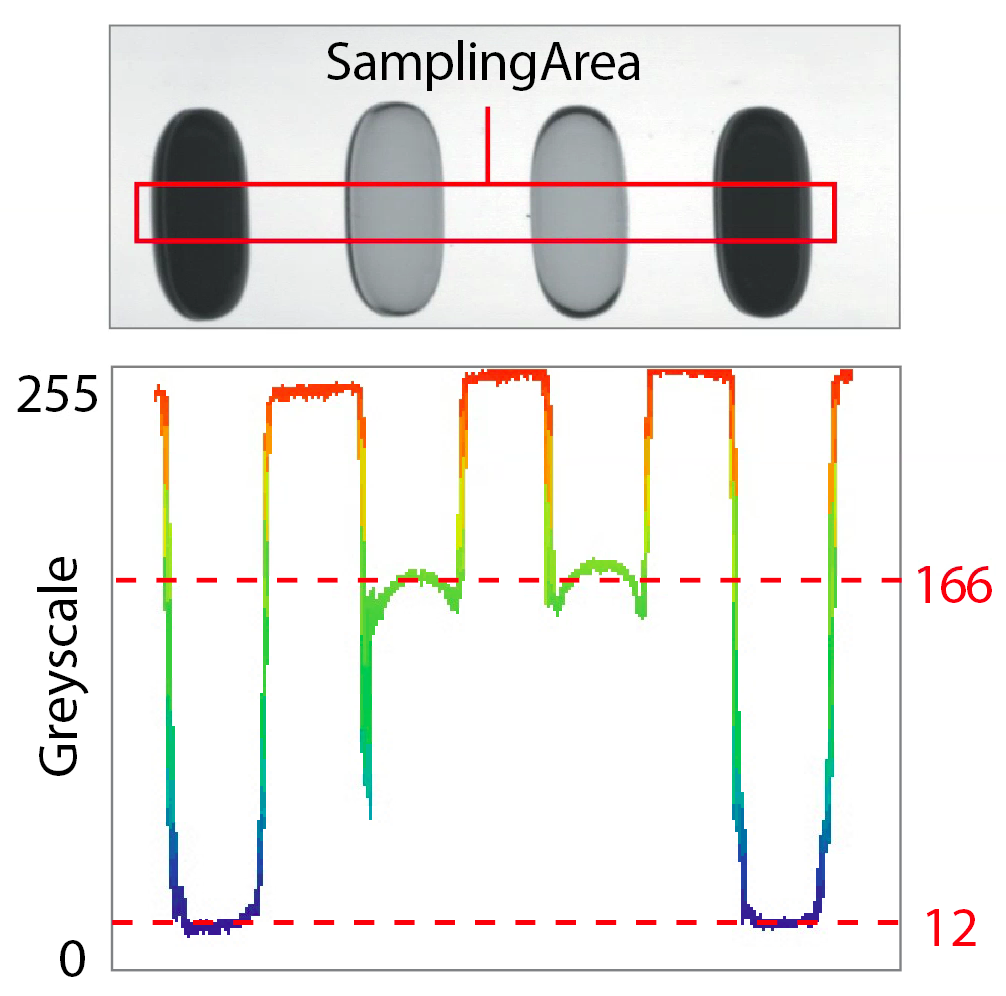
Figure 6: Capsules being viewed with a monochromatic camera yielding a contrast of 8.7% (a) and with a monochromatic camera and green filter yielding a contrast of 86.5% (b).
Neutral Density Filters
Neutral density filters are used in certain applications where it is advantageous to have additional control over the brightness of an image without changing the exposure time or adjusting the f/#. Although there are two primary types of neutral density filters (absorbing and reflecting), effect on the image is the same: uniformly lower the light that is transmitted through the lens and onto the sensor. For applications like welding, where the imager can be overloaded regardless of the exposure time, neutral density filters can provide the necessary drop in throughput without needing to change the f/# (which can impact the resolution of the system). Specialty neutral density filters, like apodizing filters, exist to help with hotspots in the center of an image caused by a harsh reflection from an object, but the optical density decreases with radial distance away from the center of the filter.
Polarizing Filters
Polarization filters are another common type of filter used in machine vision applications that allow better imaging of specular objects. To properly use polarizing filters, both the light source and the lens must have polarization filters on them. These filters are called the polarizer and analyzer, respectively. Figure 7 shows an example of how polarization filters can make a difference when viewing specular objects.

Figure 7: Images taken with no filter (a) showing high glare and with polarization filters (b) which reduce glare.
In Figure 7a, a CCD imager is being inspected with brightfield illumination and Figure 7b shows the same illumination setup with a polarizer on the light source and an analyzer on the lens. As shown in Figure 7b, augmenting the system with polarizers provides superior performance as the harsh reflections are absorbed by the filter on the lens. To ensure the maximum rejection of unwanted glare, the polarization axis of the polarizer must be angled 90° from the polarization angle of the polarizer on the lens. Otherwise, the lens will still transmit some of the harshly reflected light into the system, causing glare. It is critical to understand that filters exist to manipulate the contrast of an image to help increase the accuracy of the imaging system. Whether filtering by color or by polarization, each filter exists to solve a unique problem; it is important to understand which filters should be used for specific applications.


or view regional numbers
QUOTE TOOL
enter stock numbers to begin
Copyright 2023 | Edmund Optics, Ltd Unit 1, Opus Avenue, Nether Poppleton, York, YO26 6BL, UK
California Consumer Privacy Acts (CCPA): Do Not Sell or Share My Personal Information
California Transparency in Supply Chains Act
This content may include material that has been generated or modified using artificial intelligence (AI).
The FUTURE Depends On Optics®