


Beam Quality and Strehl Ratio
This is Sections 4.2, 4.3, 4.4, 4.5, and 4.5 of the Laser Optics Resource Guide.
In order to accurately predict the real-world performance and quality of a laser, it is necessary to understand the laser’s M2 factor, which describes the quality of the beam. Once the laser’s performance is known, defining the true performance of any optical system used with it will allow for an understanding of the final system performance. Comparing the real performance of an optical system to its ideal, diffraction-limited performance is done by using the Strehl ratio.
M2 Factor
The beam quality of a laser is characterized by the M2 factor, comparing the true shape of the beam to that of an ideal Gaussian beam. The ISO Standard 11146 defines the M2 factor as1:
In Equation 1, w0 is the beam waist, θ is the divergence angle of the laser, and λ is the lasing wavelength (Figure 1). As defined in our Gaussian Beam Propagation application note, the divergence angle of a Gaussian beam is determined by the following equation:
Inserting the found divergence angle into Equation 1 simplifies the equation for the M2 factor of a Gaussian beam:
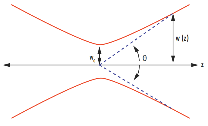
Figure 1: Illustration of the divergence angle and beam waist of a laser beam
Therefore, an M2 factor of 1 corresponds to a diffraction-limited Gaussian beam. Larger M2 factors (greater than 1) correspond to deviations from an ideal Gaussian beam. A value less than 1 cannot be achieved. The M2 factor of a Hermite-Gaussian mode is given by (2n + 1) in the x direction and (2m + 1) in the y direction.2 For example, TEM13 has an M2 factor of 3 in the x direction and of 7 in the y direction. A typical Helium Neon laser has an M2 factor between 1 and 1.1. More information on Hermite-Gaussian Modes can be found in our Laser Resonator Modes application note.
Along with a laser beam’s optical power, the M2 factor determines the radiance of the beam. The M2 factor can also be used to approximate the radius of a beam as it propagates by replacing the wavelength of a laser with the wavelength multiplied by the M2 factor found in all of the equations in the Gaussian Beam Propagation application note.3
The M2 factor is important because it represents how well a laser beam can be focused for a given divergence. Lower M2 factors correspond with a tighter focus, a more efficient use of the power within the beam, and a higher potential effective power of the laser.
Measuring M2 is not as simple as measuring the beam profile at a single plane on the laser axis. ISO 11146 dictates that five beam radius measurements must be taken at different positions along the optical axis in both the near field and the far field.4 It is possible to make a beam look like an ideal Gaussian at one specific plane without it containing any of the TEM00 mode at all (Figure 2). Even though the cross-section at that specific plane will look like a perfect Gaussian distribution, the beam will propagate very differently than a Gaussian beam and will have a greater divergence angle.5 Multiple radius measurements at different planes will quickly reveal the difference between this beam and a true Gaussian beam. The measured beam radius (w(z)) can be related to the beam waist (w0), wavelength (λ), and M2 factor by:6
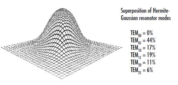
Figure 2: This beam cross-section appears Gaussian at a specific plane even though it doesn’t contain any of the TEM00 mode, illustrating the importance of making several intensity measurements along the laser axis to determine a laser’s M2 factor
One disadvantage of characterizing beams with the M2 factor compared to other beam quality parameters is that it places more emphasis on the “wings”, or lower-power density parts of the beam furthest away from the center, making it occasionally better suited for academic settings rather than industrial applications.
Beam Parameter Product
The beam parameter product (BPP) is another metric used to evaluate the quality of a laser beam. It is defined as the product of the beam radius at the beam waist and the half-angle beam divergence. It is typically reported in mm mrad, and is related to the M2 factor by:
Since the BPP is directly proportional to the M2 factor, a larger beam parameter product corresponds with a poorer quality beam. The minimum value of the BPP is λ/π and this can only occur for an ideal Gaussian beam.
BPP is commonly used to characterize fiber or semiconductor lasers with large M2 factors, as well as diode-laser fiber-coupled systems for determining the quantity of light that can be coupled into a fiber.
Power in the Bucket
Power in the bucket (PIB) is yet another metric for defining beam quality, and is often used in high power laser systems and materials processing applications. PIB describes how much laser power is integrated over a specified “bucket”, most often a spot of a specific radius at the material surface being processed. While this is a seemingly simple concept, the bucket shape in the far field must be well defined and comparisons to ideal scenarios depend on the specification of the ideal near field laser beam shape.
While there is no industry standard for the exact definition of PIB, it is most often reported as either a vertical or horizontal beam quality:7
Similarly to the M2 factor and BPP, a lower PIB value corresponds with a higher quality beam. The PIB can be visualized by plotting the fraction of power in the defined “bucket” as a function of λ/D, where D is the diameter of the near-field beam (Figure 3). The vertical beam quality is the square root of the ratio of the fraction of power in the bucket of an ideal Gaussian beam to that of the real beam at a given λ/D, which corresponds to the vertical dimension of the plot. Similarly, the horizontal beam quality is the ratio of the λ/D value of an ideal Gaussian beam to that of the real beam at a given fraction of power in the bucket, which corresponds to the horizontal dimension of the plot.
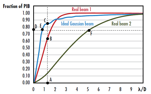
Figure 3: The vertical beam quality of real beam 1 is given by the square root of the ratio of segment AC to segment AB and the horizontal beam quality of real beam 2 is given by the ratio of segment DF to segment DE7
Circular vs. Elliptical Beams
When considering the shape of a laser beam, determining whether the laser produces a circular or elliptical beam is important. Elliptical beams may be detrimental to system performance because they will have a larger focused spot size compared to circular beams. This larger spot size leads to a lower irradiance (flux of radiant energy per unit area) than a circular beam, which in turn may require a higher power input to the laser. Semiconductor laser diodes emit elliptically-shaped beams with different divergence angles in the x and y directions because of the rectangular shape of its active region (Figure 4). Diffraction is greater for small apertures, therefore the shorter dimension of the active region will produce a more divergent beam and result in an astigmatic beam. The axis with the larger divergence angle is defined as the fast axis, while the axis with the smaller divergence angle is defined as the slow axis. Cylinder lenses are often used to circularize elliptical beams (Figure 5). For more information on cylinder lenses see our Considerations When Using Cylinder Lenses application note.
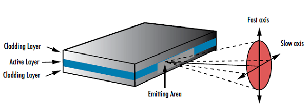
Figure 4: The geometry of laser diodes causes them to produce elliptical beams with two different divergence angles
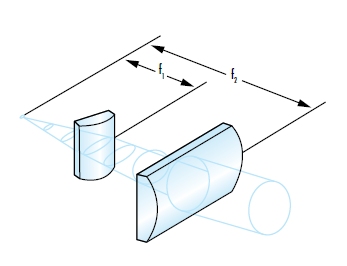
Figure 5: Cylinder lenses are often used to circularize an elliptical beam by acting on the fast and slow axes separately
Strehl Ratio
Just as the M2 factor compares the real performance of a laser to an ideal beam, the Strehl ratio of an optical system or component compares its real performance with an ideal version. The Strehl ratio of focusing optics, including spherical and aspheric lenses, is the ratio of maximum focal spot irradiance of the actual optic from a point source to the ideal maximum irradiance from a theoretical diffraction-limited optic (Figure 6).7 A Strehl ratio of 1 would indicate that an optic is perfect and aberration free. Common industry practice considers a lens “diffraction-limited” when the Strehl Ratio is greater than 0.8.
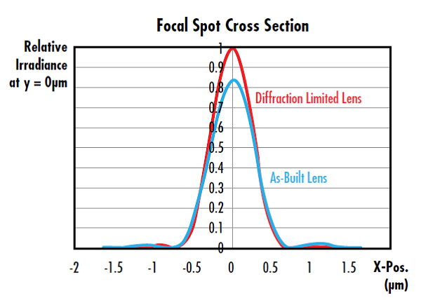
Figure 6: This lens has a Strehl Ratio of 0.826, which is considered diffraction limited because it is greater than 0.8
An optic’s Strehl ratio is approximately related to RMS transmitted wavefront error by Equation 8 where S is the optic’s Strehl ratio and σ is optic’s RMS wavefront error in waves.8 This approximation is valid when the wavefront error is <0.2 waves.
For information on how an optic’s surface irregularity affects its Strehl ratio, see our Aspheric Lens Irregularity and Strehl Ratio application note.
References
- International Organization for Standardization. (2005). Lasers and laser-related equipment – Test methods for laser beam widths, divergence angles and beam propagation ratios (ISO 11146).
- A. E. Siegman, “New developments in laser resonators”, Proc. SPIE 1224, 2 (1990)
- Paschotta, Rüdiger. Encyclopedia of Laser Physics and Technology, RP Photonics, October 2017, www.rp-photonics.com/encyclopedia.html.
- International Organization for Standardization. (2005). Lasers and laser-related equipment — Test methods for laser beam widths, divergence angles and beam propagation ratios — Part 1: Stigmatic and simple astigmatic beams (ISO 11146-1:2005).
- A. Siegman, “’Non-Gaussian’ Beam”, OSA Annual Meeting, Long Beach, CA (1997)
- Hofer, Lucas. “M² Measurement.” DataRay Inc., 12 Apr. 2016, www.dataray.com/blog-m2-measurement.html.
- Strehl, Karl W. A. “Theory of the telescope due to the diffraction of light,” Leipzig, 1894.
- Mahajan, Virendra N. "Strehl ratio for primary aberrations in terms of their aberration variance." JOSA 73.6 (1983): 860-861.
More Resources
- Aspheric Lens Irregularity and Strehl Ratio Application Note
- Considerations When Using Cylinder Lenses Application Note
- Laser Resonator Modes Application Note
- Gaussian Beam Propagation Application Note
- Laser Optics Lab Video Series


or view regional numbers
QUOTE TOOL
enter stock numbers to begin
Copyright 2023 | Edmund Optics, Ltd Unit 1, Opus Avenue, Nether Poppleton, York, YO26 6BL, UK
California Consumer Privacy Acts (CCPA): Do Not Sell or Share My Personal Information
California Transparency in Supply Chains Act
This content may include material that has been generated or modified using artificial intelligence (AI).
The FUTURE Depends On Optics®